A STUDY ON THE ENGINEERING BEHAVIOUR OF NAIROBI SUBSOIL
ABSTRACT
Nairobi City is underlain by volcanic materials that resulted from the formation of the rift valley. Some of the challenges that face design of structures in the city include: the need to develop structures in areas with poor site conditions; distress in structures that could be related to foundation conditions; encounter of unexpected subsoil conditions even after carrying out some geotechnical investigations, and; development of defects related to adjacent deep excavation.
The objectives of this study were: to investigate the qualitative and quantitative properties of subsurface materials, to establish the engineering property variations and to provide properties that represent the best estimates. Information available for this study included; Atterberg limits, grading, consolidation, swell and collapse, triaxial shear and direct shear, point load and unconfined compressive strength. Failure investigation and resistivity survey were carried out to fill the gaps in the available information. The results indicate that the engineering properties of the materials are very variable. Material property variations and the expected performance of the various subsoil materials are provided. The study concluded that before construction, it is necessary to carry out geotechnical investigations to delineate sensitive soils, determine weak and strong spots and evaluate the relationship between total and differential settlements.
Keywords: subsoil, engineering behaviour, subsurface, mechanical properties, resistivity, Nairobi.
1. INTRODUCTION
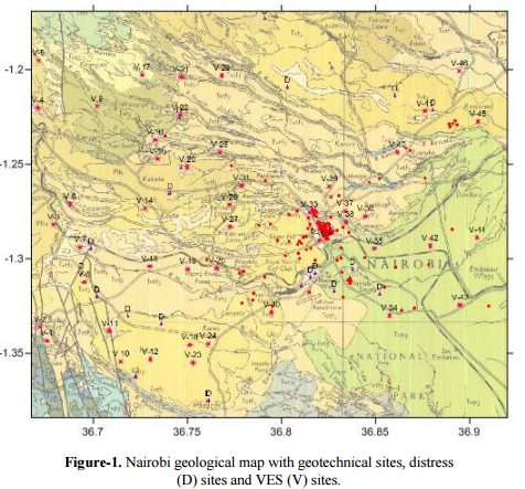
Nairobi City started in 1899 during the construction of the Kenya-Uganda Railway Line. The first settlement was started by the Survey Team that pitched tents beside the crystal clear water from the Central Highlands after working through dry arid areas. It was decided that Nairobi be made a storage depot for railway construction materials and building of permanent structures began. With the depot acting as the nucleus, the population started to grow and, by 1905, Nairobi became the capital of Kenya with a population of about 10 000 people. It became a municipality in 1919 and a city in 1950 [1]. The Nairobi City boundaries have since been revised at least five times. The population of the city has been increasing at the rate of 5.5% per annum. Increase in population has led to rapid development of structures even in areas with poor site conditions. Several parts of the city have reported distress in structures that could be related to foundation conditions in the last few decades. During construction, contractors have reported encounter of unexpected subsoil conditions even after carrying out some geotechnical investigations. There are also some reports of development of defects in structures related to adjacent excavation. Figure-1 is a geological map of the study area on which geotechnical investigation sites, distress sites (D) and vertical electrical sounding (VES) sites (V) are plotted.
The City Council has no requirement that geotechnical site investigations are carried out before construction. In most instances, geotechnical site investigations are carried out for large building projects such as bridges and tall buildings. For most residential building designs, conservative soil and rock shear strength parameters are adopted. Results of site investigation for tall structures and failure investigation for some sites within the city are available in records but not compiled in a way that they can be accessible to developers. The objectives of this study were: to investigate the qualitative and quantitative properties of subsurface materials, to establish the engineering property variations and to provide properties that represent the best estimates. Information available for this study included Atterberg limits, grading, consolidation, swell and collapse, triaxial shear and direct shear, point load and unconfined compressive strength.
2. REVIEW OF LITERATURE
Engineering properties of subsurface are investigated by direct methods such as borings and trial pits or through indirect methods such as seismic acoustic, resistivity and ground penetrating radar. Usually it is impossible to define all subsoil characteristics through field investigations and laboratory testing. Site investigation is an important part of civil engineering design whose aim is to reduce uncertainty of ground conditions by various combinations of field and laboratory testing. However, the scope of site investigations is usually dependent on the finances available and time required for carrying out the investigation. National Research Council [2] carried out a study on the adequacyof site investigations in 89 underground projects. The study concluded that 85% of the investigations did not adequately characterise the subsurface.
When geotechnical investigations are not adequate, constructors are faced with a challenge of change in assumed structural and/or subsurface conditions revealed during excavation [3]. A study by Littlejohn et al., [4] indicated that the greatest element of risk in a building project lies within the uncertainties in ground conditions. The uncertainties result in unpredictable construction costs and programming [5]. Fenton et al., [6] carried out studies on the effects of variability in soil properties on total and differential settlement of structural foundations. From the study, they concluded that unless the total settlements themselves are particularly large, it is actually differential settlements which lead to unsightly cracks in façades and structural elements, possibly even structural failure.
Richardson [7] investigated settlement in low-rise and medium-rise buildings with foundations up to 3 m depth. In agreement with Fenton et al., [6], he concluded that constructional settlement is not usually detrimental provided the structure settles uniformly or is robust enough to accommodate differential settlement. However, Richardson [7] noted that constructional settlement does not always stop; old overloaded buildings set on deep clays will not achieve equilibrium but will show slight settlement. Goldsworthy et al., [8] carried out a study entitled “Risk and Reliability of Site Investigation”. They concluded that the risk of foundation failure is heavily dependent on the quantity and quality of information obtained from a geotechnical site investigation aimed at characterizing the underlying soil conditions. Increasing the scope of the site investigation significantly reduces the risk of foundation failure, potentially saving clients and consultants large sums of money.
3. GEOLOGICAL SETTING
The City of Nairobi lies within a volcanic setting that resulted from rift valley formation. The volcanic rocks overlie metamorphic rocks of Neo-Proterozoic Era. The metamorphic rocks consist of ancient sediments which subsequently were metamorphosed as a result of high temperatures and pressures. The metamorphism is believed to have taken place in the late Precambrian to Lower Palaeozoic times. Following the metamorphism and folding, the area was subjected to erosion lasting for more than 400 million years, leaving an erosion surface dated to end Cretaceous Age. In the Upper Miocene times, phonolitic lava flowed across the eroded metamorphic surface from the edge of the newly formed Rift Valley. This lava is known as Kapiti Phonolite since it underlies the Kapiti Plains. The Kapiti phonolite is a rock with large white crystals of feldspar and waxy-looking nephelines set in a fine-grained dark-green to black ground mass [9]. Some exposures reveal the vesicular nature of parts of the phonolite and small patches of calcite and zeolite-filled amygdales are common.
The Kapiti Phonolite is overlain by pyroclastic rocks with interbedded lacustrine sediments which were deposited in a large lake or a series of lakes that extended over an area of 7000 km² [10]. These rocks are referred to as Athi Tuffs and Lake Beds or simply as Athi Series. The colour of the tuffs ranges from black to grey to yellow but are generally fine-grained. The beds contain plant remains and show signs of desiccation. The Athi Series is divided into three parts: the Upper Athi Series, Middle Athi Series and Lower Athi Series. The Upper Athi Series (UAS) mainly consists of sandy sediments and tuffs, clays being subordinate. The Upper Athi Series also includes intercalations of thin non-porphyritic black basalt flows.
The UAS is generally soft and friable in character with a hard yellow tuff band (6 m) forming a good marker horizon. Generally, the series is characterized by the presence of obsidian but with much lateral variation. In between the UAS is Mbagathi Phonolitic Trachyte, which is porphyritic lava with tabular insets of feldspar. The most striking feature of the Mbagathi Phonolitic Trachyte is its texture of crowded feldspar laths set in a gray-brown matrix, the colour of which is emphasized by rusty brown weathering and alteration products. In many places Mbagathi Phonolitic Trachyte is vesicular and the feldspars, which are up to a centimetre in length, are frequently flow oriented [9]. Middle Athi Series (MAS) consists of basalt flows and basalts sands and agglomerates. The lavas show abundant insets of feldspar and the sands often have a clay matrix [11].
Lower Athi Series (LAS) are predominantly clayey deposits between the basaltic MAS and the uppermost flow of the Kapiti Phonolite [9]. In some places the LAS lies directly on the metamorphic rocks. The thickness of the Athi Series is variable depending on the shape of the erosion surface at the time of deposition. The maximum established thickness of the Athi Series (305 m) is at Nairobi City Centre [11]. Overlying the Athi Series rocks are the Nairobi and Kandizi phonolites. Nairobi Phonolite is dark- grey, porphyritic lava with tabular insets of feldspar and a few flakes of biotite. The lava is distinguished in drilling samples by the presence of biotite. The Kandizi phonolite is non-porphyritic lava with only very sporadic insets feldspar, biotite being absent. The groundmass of Kandizi phonolite is like that of the Nairobi Phonolite. In some places, Nairobi Phonolite is overlain by Nairobi Trachyte. Nairobi Trachyte is greenish grey, occasionally porphyritic with tabular phenocrysts of feldspar. The groundmass is fine-grained with a silver lustre. At Upper Hill it is separated from Nairobi phonolite by a few metres of agglomeratic tuff. Nairobi trachytes have great affinities to phonolitic rocks though lacking in nepheline. Ngong’ Volcanics overlie Kandizi Phonolite and overlap onto the Mbagathi Phonolitic Trachyte. They are dark-grey lavas of basalt and nepheline interbedded with sands. In boreholes they occur immediately below Nairobi Trachyte. Kerichwa Valley Series (KVS) is a group of pumice-rich trachytic tuffs and agglomerates younger than the Nairobi Trachyte. The tuffs overlie the Nairobi Trachyte and nearly every other older formation and have some resemblance to some of the Athi Tuffs and Lake Beds. The deposits of KVS buried a pre-existing landscape, the former valleys of which are now being re- excavated to reveal Nairobi Trachyte and Nairobi Phonolite. The tuffs range from cemented fine-grained, wind-sorted pumiceous ash to agglomeratic tuffs with rock fragments up to 0.5 m size. The tuffs are referred to as “agglomeratic tuffs” not agglomerates because of the larger proportion of fine material that forms the rock. The colour of Kerichwa Valley tuffs is generally yellow, grey or black. The Series cannot be traced to any volcanic vent and it is probable that they are the result of rapid pressure release following rift faulting and graben-forming collapse. It is thought that the centre of volcanic activity during this period was located somewhere in the City Centre because it is unlikely that these pyroclastic materials were ejected from a far away vent [12]. The north of the study area is covered by Kabete Trachyte, Karura Trachyte and Limuru Quartz Trachyte.
These trachytes overlie the Kerichwa Valley Series. Kabete Trachyte is greenish-grey porphyritic rock that weathers to soft grey colour and has similarities withNairobi Phonolite. It has limited lateral extent and has a maximum thickness of 30 m in Kabete. Karura Trachyte is fine-grained, dull grey to lustrous rock, similar to NairobiTrachyte but higher in succession and spotted when weathered.
4. MATERIALS AND METHODS
Comprehensive subsoil data is available from several geotechnical investigations carried out at building sites and failure investigations performed at different locations and depths. This study obtained various test results for 182 sites. The results of particle size analysis were plotted on grading curves, liquid limit and plasticity indices were plotted on plasticity charts to study the plasticity and compressibility of the soils. Triaxial and direct shear test results were used to compute the shear strength of the soils. Collapse, swell and shrinkage limit results were used to in relation to the defects in structures. Unconfined compressive strength (UCS) of the rocks was calculated from results of uniaxial compressive strength and point load tests. Bearing capacity of the rocks was calculated using Goodman [13] formula.
A factor of 10 was applied on the ultimate bearing capacity to obtain the allowable bearing capacity. The following characteristics of the Nairobi subsoil led to the use of this high factor: the heterogeneous nature; existence of highly fractured and decomposed rocks that are subject to development of rupture surface when loaded; presence of very weak layers underlying strong layers, and; the presence of groundwater at some sites [14]. In investigating distress in structures, undisturbed samples were taken from underneath the foundations and flooded and non-flooded oedometer tests were carried out at three different loading conditions. Load settlement curves were drawn from the results of oedometer tests. Electrical resistivity survey was carried out for areas without geotechnical test and failure investigation results so as to compare with the mechanical properties at known sites. The preliminary study involved identifying the suitable sounding sites and seeking permission from relevant authorities to use the site on a specified day. The sounding centres were selected based on the need to bridge the gap in knowledge about the subsurface at the locality by relating the nearest bore log information to the geoelectric properties and on the availability of space for carrying out geophysical resistivity survey. The resistivity survey was conducted using a
WDDS-2 Digital Resistivity Meter manufactured by Benteng Digital Control Technology Institute in China. Vertical electrical sounding (VES) was carried out at 48 sites (Figure-1) using Schlumberger array with current electrode distances ranging from 80 m to 500 m. Apparent resistivity values were converted into 1- D sounding curves and layered resistivity models using the Earth ImagerTM software. The software has the capability to detect the geoelectric layers up to 0.55; so for example if AB/2 was 100 m it could only detect layers clearly up to 55 m. The subsurface profiles based on the boreholes adjacent to the VES site were drawn using StraterTM written by Golden Software, Colorado. A line log of resistivity versus depth could also be drawn to compare with the subsurface profile. The assumption made in the 1- D interpretation is that the layers are homogeneous and horizontal. Correlations were made between the resistivity values and the mechanical properties of the subsoil using various formulae. The equation for relating resistivity and UCS derived from a combination of two experimental results by Keller [15] and Kate and Sthapak [16] expresses a generalized relationship between UCS, qu (MPa) and resistivity, ρ (ohm-m) in the form of an equation given below [17].

Deshmukh and Gokhale [18] studied the variation of point load strength and resistivity for saturated coalmine and observed linear increase in Is50 with increase in ρ. The variation of punching shear strength, τp with electrical resistivity of rocks obtained by Gokhale [19] on igneous, sedimentary and metamorphic rocks depicted a trend of linear increase in τp with increase in ρ on log scale. The generalised relationship between punching shear strength and ρ (ohm-m) is given as follows:

Keller [15] reported curvilinear increase in resistivity with increase in Young’s Modulus on log-log plot for thermally soaked Palaeocene basalt. Donaldson [20] reported decrease in compressibility and increase in modulus of elasticity with increase in resistivity for monzonite. Kate and Rao [21] reported curvilinear increase in resistivity with increase in both the tangent modulus of elasticity as well as Poisson’s ratio for dry sandstones. All the above relations indicate that higher resistivity yields better mechanical properties.
5. RESULTS
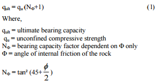
Figure-2 presents the subsurface profile, strength classification [22] and allowable bearing capacities for some sites within the city centre. The geological successions in the three boreholes are different, and in general the bearing capacities of the subsoil are low. Figure-3 presents a comparison between three borehole logs at Serena Hotel and resistivity curve and layered resistivity model for the nearby Uhuru Park. Water was encountered at 2 m depth and this corresponds well with the layered model. A water supply borehole at Serena Hotel indicates that much of the subsurface is clayey or decomposed up to 130 m depth with thin sound layers. The sound layers were suppressed in the layered model.
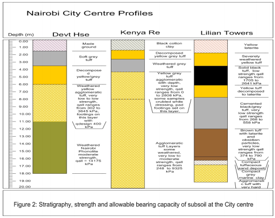
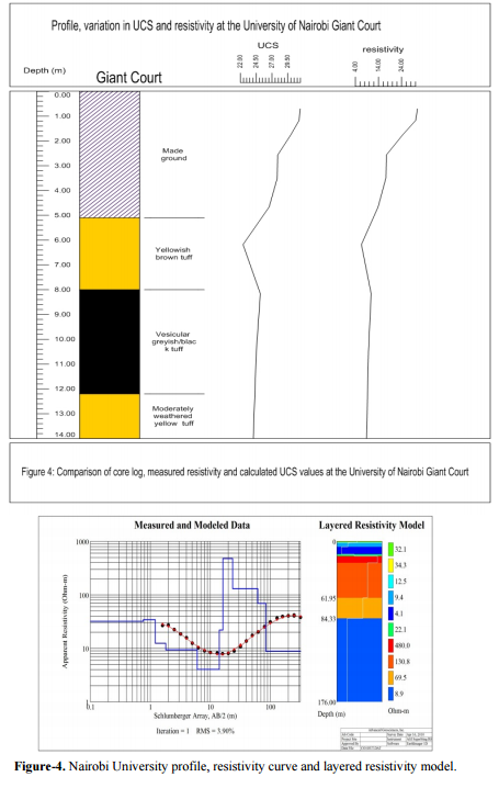
Figure-4 is a representation of borehole log and resistivity model at University of Nairobi Sports Field. Shallow groundwater was encountered at 1.8 m in the geotechnical boreholes. The university water supply borehole (C-10497) indicates that aquifers were encountered at 152 m and 230 m. The first aquifer is within the low resistivity (8 ohm-m) layer in the VES curve. It is worthwhile to note that the resistivity starts to rise on encounter of the black tuff which has been found to be competent elsewhere within the city
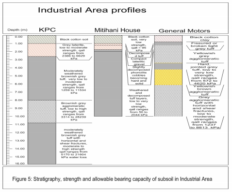
Figure-5 is a comparison of three profiles within Industrial Area. Most of the materials are weathered throughout the length of the boreholes except for the agglomeratic tuffs at the KPC site. Some structures within the vicinity of Mitihani House have reported distress in structures. Many structures at the nearby Kongoni Primary School are out of use.
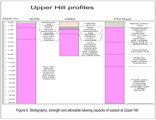
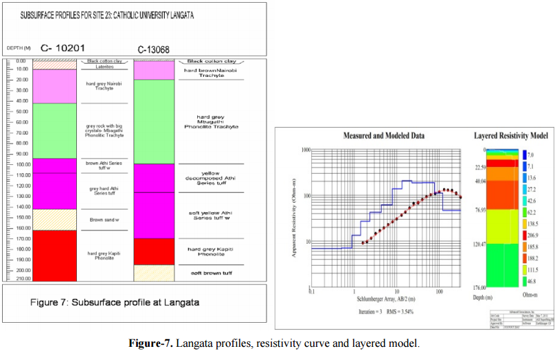
The subsurface formations at the Upper Hill area comprise of a thin layer of overburden underlain by Nairobi Trachyte as shown in Figure-6. At Ardhi House, the subgrade materials are poor with regard to load carrying capacity. The hard and solid trachyte found in the three sites suddenly and surprisingly changes and exhibits high degree of decomposition on reaching this site. The allowable bearing capacity of the trachyte was found to range between 400 kPa and 3768 kPa. This sudden change created difficulties in the design of foundations. The other office sites in the vicinity e.g. Works Office have a very shallow overburden at 0.3-1.8 m followed by fractured trachyte. The trachyte makes distinct noise when hit by a geological hammer, a characteristic of phonolites but lacks nepheline as observed in thin section. The Upper Hill area is less than a kilometre away from the City centre where Nairobi Trachyte is not encountered. Figure-7 presents profiles of two Langata area boreholes that are less than 100 m apart. The resistivity values at Langata are low at the surface owing to the state of the subsoil and continue to rise within the Nairobi Trachyte and Mbagathi Phonolitic Trachyte. The resistivity values start to fall within the Athi Series, which are the main aquifers in this area.
6. DISCUSSIONS
The thickness and engineering properties of the various subsurface materials vary from place to place and even within construction sites such that it is not possible to provide one stratigraphic profile relevant in geotechnical terms for the entire study area. Given that the formation of the Nairobi subsoil took place over a very long period of time, the upper contacts of the geological units as well as the weathering grades vary from place to place depending on the shape of the eroded surface at the time of deposition. Several volcanic flows can be observed within each geologic unit. The strength of such flows increase downwards as the upper part is found to be weathered or decomposed.
Although a geotechnical borehole at Loita House at the City Centre indicates that sound rock exists at 59 m -75 m depth, borehole logs at many other places indicate that the rock is weathered or decomposed to at least 150 m. The geotechnical borehole at Loita House was drilled deep into the ground so as to determine the depth of bedrock. While it was believed that finally the bedrock at the City Centre had been encountered, the profiles in the nearby water supply boreholes indicate that it just terminated before encountering a larger thickness of decomposed materials. Several other weathered layers are found up to 472 m where the metamorphic rocks are encountered. At Hilton Hotel the strata are decomposed at 78 m-130 m, Kenya Re at 88 m-130 m, Lilian Towers at 88 m -102 m. The thickest decomposed material is recorded at ICRAF Gigiri (103 m-304 m) while at Rosslyn area the subsurface consists of heterogeneous sediments, sand and silt without any intervening tuffs. In general the thickness of weathered materials in the city is larger than thickness of the sound and fractured rocks.
The Kerichwa Valley tuffs are stratified in alternating thin and strong layers that include the following: fine-grained yellow (yellowish grey/grey) tuffs, dark grey to black tuff and fine-grained yellow tuff becoming agglomeratic with depth. However the succession at Lilian Towers at the City Centre is somewhat different from the others; brown tuff, marine clay and coarse-grained (probably the agglomeratic tuff) tuff are recovered at this hole. The brown tuff encountered at Lillian Towers site is also found at Union Towers and at various sites along Tom Mboya Street. The profile at the University of Nairobi Main Campus is as follows: 0-1.5 m black cotton clay, 1.5 m-8 m decomposed yellowish brown tuff, 8 m-18 m grey tuff followed by Nairobi Phonolite. The correlation between the two boreholes seems to support report No 182 at Materials Department that University Way and Moi Avenue are along the course of an old river. The range of UCS values for most of the KVS tuffs is 2 MPa to 5 MPa in which case the allowable bearing capacity ranges between 500 kPa and 1400 kPa. At several depths at Reinsurance Plaza at the City Centre, the tuff crumbled while dressing. Core logs from many sites at the city centre indicate that the tuffs could not be sampled as a core at depths ranging between 3.7 m and 12 m. At the NSSF site in Karen a very low strength of 0.745 MPa was encountered at 7.4 to 7.7 m depth with a allowable bearing capacity of 201 kPa.The tensile strength can be taken as 10% of UCS but varies from 5-25% while the flexural strength can be taken as twice the tensile strength [24].
At the City centre most of the structures are supported on Kerichwa Valley tuffs or their weathered equivalents. The yellow tuffs are found up to depths of 6 m below the ground surface. The yellow tuffs sometimes extend up to depths of 6 m below the ground surface and therefore support most of the shallow foundations structures set at 1.5 m to 2 m depth. Excavations made through intact yellow tuffs are fairly stable and do not need any form of support. Darker yellow tuffs are described as brown tuffs at some sites and give rise to brown highly plastic clays when weathered. From test results, intact yellow tuff has allowable bearing capacity of 500-700 kPa and when horizontally and diagonally fractured with clay infills, the bearing capacities are in the range of 350-500 kPa. Decomposed yellow tuff has allowable bearing capacities in the range of 250-300 kPa. Design pressures on the yellow tuff have been in the range of 250-400 kPa. Excavations made through the fresh yellow tuffs are fairly stable and do not need any form of support.
From the grading tests, it is clear that the soils formed from decomposition of yellow tuffs consists of large fractions of either silt or clay or silt and sand, the gravel content being nil or very small. The soils are poorly graded and hence only one curve has a sigmoid shape. The soils have high to extremely high plasticity, high natural moisture content and expansive properties. When dry the clays are stiff and fissured. Coarser- grained yellow tuff is weathered to lateritic clay with physical characteristics of laterites but with low bulk densities and sensitive to moisture changes. Structures supported on the clays or lateritic clays have undergone distress of varying magnitudes depending on the amount of moisture accessed under load. Darker yellow tuffs are described as brown tuffs at some sites and give rise to brown highly plastic clays when weathered.
Black tuffs are very competent rocks with allowable bearing capacity of 1600 kPa. They are encountered at 3 m to 8 m below the ground surface. The upper and lower parts of the black tuff are grey or dark grey, the middle part is black and the most competent. Design pressures for most structures resting on the black tuff are in the range of 400-800 kPa. The reason why most structures supported on the black tuff are not designed for higher pressures is the presence of yellow tuff underneath that is often weathered to soft and plastic clay. Design values greater than 400 kPa have been used at sites where the underlying yellow tuff is not so weathered.
Yellow agglomeratic tuffs consist of phonolite boulders poorly cemented in a matrix of yellow tuff. Yellow agglomeratic tuffs have been found to be soft and unstable when in contact with water and when weathered they form gravelly clay. The agglomeratic tuffs are encountered at depths starting from 6 m and can extend up to 20 m. The bearing capacity of the agglomeratic tuffs is found to be low (less than 300 kPa) when the matrix is tested and very high (up to 2100 kPa) when the boulders are tested. For instance at a depth of 8 m at KPC site in Industrial Area and 5.8 m to 11.8 m depth at NSSF Karen very high strength values corresponding to the strength of Nairobi Phonolite are recorded. These high strengths are not recorded from the adjacent geotechnical boreholes indicating the tuffs are agglomeratic, and possibly the adjacent boreholes recovered the matrix part of the agglomeratic tuff. A design bearing pressure of 350-400 kPa has been used on these tuffs. Because of the poor bonding between the fine matrix and the boulders, excavations done through the agglomeratic tuff are susceptible to collapse when left open. A method of shoring of excavation should be provided to avoid development of slip circles. In very deep excavations, it has been found that the agglomerates cave in when excavating though the competent phonolites or trachytes below that shake and loosens the agglomerates.
Another group of subsoil covering the Nairobi surface includes alluvium, clays and swamp soils occupying former river valleys or swamps. The soils are slightly overconsolidated and thus compressible. They cover the City Centre from Loita Street where they have been noted at Nyati House and Caltex House up to the foothill of Nairobi Hill including Uhuru Park and University of Nairobi Sports grounds. They underlie most of the structures lining Uhuru Highway. The thickest alluvial deposits of the plastic clays at the City Centre are found at the Lutheran Church. The clays are siltier but still thick at View Park Towers, Grand Regency Hotel and Continental House. Along Kirinyaga Road, the deposits are clayey silt and more liable to collapse as occurred during construction of Parsonic Hotel. Elsewhere in the world [24], the silty clays have been found to be liable to liquefaction during earthquakes. The swamp soils have very large thicknesses in Karen Estate (10 m) Madaraka Estate (8 m) Adams Arcade, Woodley and Jamhuri Estates (8 m) and Garden and Marurui Estates (6 m). At most localities, these soils are saturated with very unusual Atterberg limits and have high compressibility when loaded. Design pressures of 75 kPa have been used on the swamp soils. Old structures supported on these soils in Garden Estate, Karen and Madaraka/ Nairobi South areas have experienced distress more than five years after construction. According to Richardson [7] buildings that experience settlement several years after construction may have been overloaded.
A glance at the geological map indicates that almost all areas covered by the alluvium, clays and swamp soils have reports of distress in structures except for Dagoretti area. In Karen, the alluvial soils are closely related with faults for instance at the Karen Police Station and Warai North Road where they are associated with distress in structures. Defects in structures are also reported for areas in the vicinity of these soils indicating that they could be extending beyond the exposure limits indicated on the geological map. The colour of the sensitive soils varies from yellow to white to brown to black and red. This shows that colour cannot be a means of recognizing these soils at a site. Before constructing in the vicinity of these soils, it is important to do a site investigation and test samples for Atterberg Limits, particle size distribution and for collapse and swell to avoid designing foundations that are likely to fail [8]. A good starting point before design of any structure should be study of the geological map, borehole records and any history concerning the site.
Nairobi phonolites when fresh are the most competent materials in the study area. When fractured they are laterised along cracks and on further weathering they form a boulder bed. Nairobi Phonolite is encountered at various depths starting from 14 m. Tested unconfined compressive strength values for Nairobi Phonolite are generally moderate to high as observed at Central Bank of Kenya site. The values range from 16.54 MPa to 108 MPa while allowable beating capacity ranges of 4467 kPa to 29463 kPa. Because of the depth at which the phonolite occurs, only one foundation excavation (Hazina Towers) has exposed the upper weathered portion of it. The lift shaft of the building is supported on the phonolite. The rock is strong for supporting multi-storeyed building but care must be taken when excavating through it because the strong vibrations during drilling undermine the upper weaker materials. A borehole drilled in 1949 at “Mansion House” at the City Centre (C-792) backfilled by 20 m when drilling through the phonolite. Later boreholes have used casing or bentonite slurry to prevent cave-in.
Karura Trachyte, Limuru Trachyte and Kabete Trachyte are very competent rocks when fresh. The trachytes are generally fine-grained and weather to red/brown soils or plastic clays with low density and sensitive when soaked with water under load. The plasticity is higher when the soils occur in a valley. In addition, the soils formed from Kabete and Karura trachytes cave in when boreholes are drilled through them and are as such cased in most cases. They are also subject to burrows and termite sinkholes. A system of shoring is required when excavating these soils for foundation placement.
Nairobi Trachyte has moderate to high unconfined compressive strength though few spots of low and very low UCS values are recorded at some sites. At the Library site along Ngong Road the UCS ranges from 12MPa to 27MPa, at NCPD site it ranges from 2MPa to 80MPa. The minimum qall is 409 kPa recovered from a depth of 3.85 m at PTA Plaza at Upper Hill while the maximum qall is11673 kPa at a depth of 8 m at NCPD site at Community. The strength of the Nairobi Trachyte is very low to moderate at the Hill Plaza site. When weathered, Nairobi Trachyte forms reddish brown plastic soil with very little gravel content. Tests show that it settles when loaded and collapses when flooded; it can settle by 84 mm when flooded while loaded by 200 kPa. An allowable bearing pressure of 150 kPa has been used on soils formed from Nairobi Trachyte. Some of the structures that have undergone distress in Langata and Karen areas are supported on these soils.
The ultimate and allowable bearing capacities calculated by the Ramamurthy formulae are more than tenfold higher than the tested values. The calculated values cannot be used for estimating the bearing capacity of the ground for design purposes but can be used to study the overall homogeneity of the subsurface. They can therefore be confirmatory for areas investigated by boreholes or other direct means. When the values are compared with tested properties established from core logs, they give an insight into the subsurface.
Ramamurthy [17] found that resistivity values of <75 ohm-m in soils and <200 for hard/fractured rock indicate the presence of water in the voids. However, the measured resistivity values in Nairobi are generally less than 200 ohm-m because they represent the average along the path travelled by the current that is weathered or decomposed. Higher values are recorded for near surface layers and are probably so because the field work was carried out at the end of a long dry season. Resistivity values for bedrock can be several thousand ohm-m (Telford et al., 1990).
Ramamurthy [17] also found that geophysical interpretation of mechanical properties of the subsoil shows significant changes and trends in the subsurface that match very closely with well log data and resistivity log. Limitations of the geophysical method are that the models used for interpretation of VES apply to homogeneous, semi-infinite layers, as they may occur in sedimentary areas. Using the same models in areas with sometimes extremely variable thickness and where the top of the layer can be very disturbed is an extrapolation, and results such as mathematically interpreted true resistivities and thickness may be subject to caution [25]. A formula given by Kahraman et al., [26] does not produce more useful values of UCS. This is because it produces 50 MPa UCS values when the resistivity is close to zero, implying that a compressive strength is obtained even for pure water.
Kahraman and Alber [27] correlated the electrical resistivity values obtained from electrical impedance spectroscopy measurements with the corresponding physico-mechanical rock properties for the eight different samples cored from a fault breccia. They found significant correlations between resistivity and physico-mechanical rock properties. Vipulanandan and Garas [28] investigated the electrical resistivity and mechanical properties of carbon fibre-reinforced cement mortar (CFRCM). They developed some empirical relations for the specific electrical resistivity to unit weight, Young’s modulus and pulse velocity. Kahraman and Yeken [29] performed laboratory experiments of resistivity on igneous rocks saturated in brine and related the measured resistivity with tested values. They obtained values of UCS ranging from 50.2 MPa for volcanic bombs to 202.9 MPa for basalts but concluded that the effect of inclusion of stronger (and weaker?) rocks needs to be investigated. The UCS values calculated from resistivity measurements of the study area range from 20 MPa to 54 MPa. These ranges of values
therefore are close to those obtained for the volcanic bombs.
6. CONCLUSIONS
Variability of engineering properties of the subsurface materials in Nairobi calls for thorough geotechnical investigations before design of structures. This is especially important because new structures are being constructed in areas initially thought as unsuitable for construction. During site investigation, it is necessary to locate stronger and weaker zones and investigate the relationship between total and differential settlement. Care should be taken when designing in the vicinity of alluvium, clays and swamp soils because overloading these soils leads to distress in structures. Resistivity measurements taken within a site can complement direct site investigation methods since they yield relevant results.
 ENGLISH
 Chinese
 Russian

