Investigate the landslide internal structure and the groundwater circulation by Resistivity Tomography
1. Introduction
Translational landslides, which develop in nearly horizontal bedrock composed of sandstone and mudstone where the dip angle is commonly 3°–5°, are typical geological hazards in the Three Gorges reservoir area and Sichuan basin in Southwest China (Kong and Chen, 1989). Translational landslides are notable for their complex formation mech- anisms, difficult identification, and serious destruction. Rainfall acts as the most common triggering factor for the initiation and reactivation of translational landslides. Under intense rainfall conditions, water can percolate into shear fractures or creep-tensile fractures in landslides, which increases the pore water pressure and decreases the effective shearing resistance of a sliding surface (Zhang et al., 1994; Van Asch et al., 1999; Fan et al., 2009). Thus, it is essential to estimate the thick- ness of sliding material, locate the sliding surface, and characterize the groundwater circulation within translational landslides to analyze their mechanisms and for hazard prevention. The widely used direct techniques (e.g., borehole, piezometer, incli- nometer, and laboratory tests) yield true parameters on the lithological, hydrological, and geotechnical characteristics of landslide bodies.
However, these techniques provide information at a specific point in the subsoil, and it is costly to evaluate the spatial distribution of param-eters using a large number of probes and tests in landslides. Given the advantages, including low cost, of non-invasive measurements, several geophysical techniques such as electrical resistivity tomography (ERT) have been used for the geological exploration of landslide areas that are characterized by complex geological settings (Jongmans and Garambois, 2007; Niesner and Weidinger, 2009; Perrone et al., 2014).
These geophysical techniques, which provide spatial geophysical infor- mation on landslide materials, are beneficial supplements to conven- tional geotechnical measurements. ERT can image 2D or 3D resistivity distributions using larger numbers of four-electrode measurements. The electrical resistivity of landslide materials is mostly influenced by the lithology, porosity, and water content of soils (Rubin and Hubbard, 2005). In addition, the increase in water content or hydrostatic pressure can play an important role in the triggering mechanisms of landslides (Fan et al., 2009). Therefore, ERT can provide valuable information for landslide analysis and early warning. Some recent works have shown that the ERT technique can be used to define the geological setting of subsoils, reconstruct the ge- ometries of landslide bodies, locate possible sliding surfaces and lateral boundaries to evaluate the groundwater conditions for estimating the dynamic behaviors of landslides (Suzuki and Higashi, 2001; Perrone et al., 2004; Lapenna et al., 2005; Jomard et al., 2007; Grandjean et al., 2011; Carpentier et al., 2012; Travelletti et al., 2012).
In this paper, four 2D ERT profiles were conducted in the southern area of the Kualiangzi landslide,which is a typical translational landslide located in Southwest China. The thickness of the sliding material anddepth of the sliding surface were estimated using the ERT profiles, drill cores, and inclinometer data. Moreover, the groundwater circulation in the landslide was characterized by analyzing the variations in electrical resistivity and groundwater level.
2. Geographical, geological, and geotectonic settings
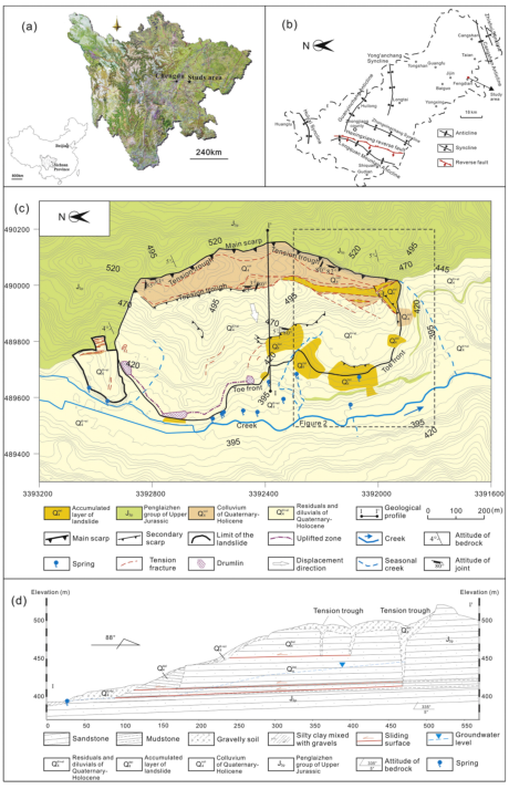
The Kualiangzi landslide is located 65 km southwest of the city of Deyang, Zhongjiang County, which is in the Sichuan province, China (Fig. 1a and b). The landslide area lies within the climate region of the subtropical humid monsoon, and the average annual precipitation is 844.5 mm. More than 80% of the total precipitation is concentrated in the rainy period from June to September, during which the rainfall is characterizedbyitslongduration,high frequency, and large cumulative precipitation. The landslide belongs to the geomorphic unit of tectonic erosion, a deep mound with a width of 50–300 m and a valley depth of 100–170 m.
The landslide is located in the north wing of the Cangshan anticline, and the bedrock generally dips to NW20°–30° at an angle of 2°–5° (Fig. 1b). There are no faults or historical destructive earthquakes in the study area. The height relief between the main scarp and the toe front is approximately 110 m. The area of the landslide is 0.51 km 2 , and the volume is 2.55 million m 3 (Zhai, 2011; Xu et al., 2015). The main body of the landslide is 360–390 m long, 1100 m wide, averages 50 m in thickness, and has a maximum thickness of 80 m (Fig. 1c and d). The rear edge of the landslide is the main scarp, which has a N–S orientation.Theleadingedge iscomprisedof thelocal collapse, an uplift belt, and seasonal springs.
The Kualiangzi landslide was always in a state of slow creep to the west, although the displacement could accelerate under conditions of intense rainfall in the flood season. At the beginning, some bead-like soil holes deeper than 50 m were found on the surface at the rear edge of the landslide and were gradually connected by a large and long crack. The first rapid acceleration in the displacement occurred due to intense rainfall in the flood season of 1949, which produced a large-scale tension trough extending in the N–S direction (Fig. 1c and d). The second rapid acceleration in the displacement was caused by a strong rainfall in the flood season of 1981. A large number of houses were destroyed by landsliding, and the residents were all forced to relocate. The tension trough close to the main scarp was significantly widened to a length of 1km and a width of 60m in the following several decades. In addition to the large scale tension troughs,many minorten- sion fractures were induced by the creeping of the landslide. According to the exposure in the scarps, two sets of subvertical joints developed with trends of NW10°–20° and SW10°–29° and dipping angles of 80°–85° and 72°–82°, respectively (Fig. 1c).
The surface of the landslide is primarily covered by a layer of resid-uals and diluvials (Q 4el + dl ), of which the ingredients are silty clay mixed with gravels.The thickness of the residuals and diluvials generally ranges from 1 m to 13 m. The bedrock of the landslide is sandstone interbedded with siltstone and mudstone and dips to NW20°–30° at an angle of 2°–5°. The sandstone belongs to the Penglaizhen group, which formed in the Upper Jurassic period (J 3p ). The thickness of the sandstone ranges from tens of meters to several meters. The mudstone, which has good water-absorbing structures and low strength, consti-tutes the main materials of the sliding zone (Fan et al., 2009; Zhai, 2011; Li, 2014; Xu et al., 2015). The thickness of mudstone ranges from 0.5m to 2m around the main sliding surface,according to the drilling cores (Fig. 1d). The unconsolidated formation in the tension trough is colluvium comprised of rock blocks, gravels, and breccias (Q 4col ). The diameter of the largest rock blocks could reach 5 m. The thickness of colluvium ranges from 51 m to 72.9 m (Zhai, 2011).
The groundwater in the landslide flows in the direction from the tension trough to the toe front. The joints at the rear edge of the land- slide provide infiltration channels for the rainwater into the inner slope during the rainy period. The tension trough plays an important role in the storage of groundwater. The groundwater level was generally higher than the sliding surface in the flood season. In addition to three seasonal creeks, a large number of seasonal springs along the toe front act as the main discharge of groundwater. The flow rate of the springs is proportional to the rainfall, according to the survey.
3. Investigation methods
3.1. Core drilling and inclinometer measurements
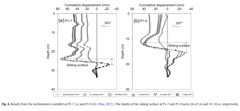
Since 2010, comprehensive engineering geological exploration has been carried out in the landslide area. Twenty-three boreholes were drilled in the southern area of the landslide in 2010, 2013, and 2014. Their locations and characteristics are presented in Fig.2 and Table1, re- spectively (Zhai, 2011; Li, 2014). The lithology, stratum thickness, core recovery rate, and static groundwater level in each borehole were re- corded. Moreover, the deep cumulative displacements were measured six times with inclinometers installed at P1-7 and P1-9 from 28 Decem- ber 2010 to 2 May 2011 (Zhai, 2011). The measurement interval of the inclinometers was 0.5 m downwards from the ground surface, and the lengths of the inclinometers in P1-7 and P1-9 were 33.5 m and 25 m, respectively. The depth of the sliding surface was evaluated by the lithology and deep cumulative displacement.
3.2. Field real-time monitoring
The hourly surface displacement, rainfall, groundwater level, and groundwater pressure were monitored in real time using GPS (BDStar Navigation), a pluviometer, osmometers, and piezometers (Geoken), respectively, which were mainly arranged in the southern area (Fig. 2). Some osmometers and piezometers (i.e., P1-1, P1-2, and U1-2) were broken by the creeping of the landslide. The data from osmom- eters U1-1 and P1-3 and piezometers U1-3, U1-4, and U1-5 from 1 June 2013 to 31 December 2013 were used to evaluate the characteristics of the groundwater circulation (Li, 2014). The groundwater level was cal- culated from the osmotic pressures in U1-1 and P1-3. Abnormal hourly data were first deleted,and the daily values of the surface displacement, rainfall, and groundwater level were then calculated.
3.3. ERT survey
Four ERT profiles were conducted byusinga Wenner–Schlumberger configuration in the study area. Their locations and measurement parameters are shown in Fig. 2 and Table 1, respectively. The A–A′ and B–B′ profiles were oriented E–W, and the C–C′ and D–D′ profiles were oriented N–S. The A–A′ and D–D′ profiles were measured in the dry period (i.e., from October to the following May) and the rainy period
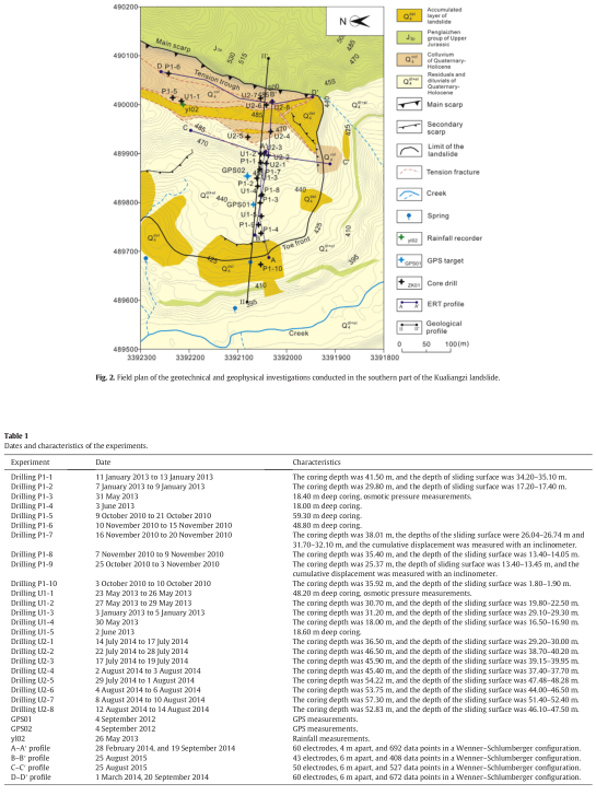
(i.e., from June to September) to evaluate the characteristics of the groundwater circulation. A WDA-1 apparatus (China) was used to make the ERT measurements. The apparatus is a single-channel 2-D electrical survey system that uses a large number of electrodes (60 or more), which are connected to a multi-core cable. An electronic switching unit in the apparatus was used to automatically select the relevant four electrodes for each measurement. For all of the profiles, the measurements were repeated three times and completed in approximately 90 min. To build usable data sets for ERT processing,apparent resistivity data with relative errors greater than 2% were first deleted. Then, the arith- metic mean of the data from the three repeated measurements wascal- culated, and the apparent resistivity data sets were built. The apparent resistivity data were then inverted using the Res2dinv software based on the least-squares method (Loke and Barker, 1996; Loke, 2007). For the A–A′ and D–D′ profiles, resistivity ratio tomographies for the rainy and dry periods were also calculated to evaluate the groundwater circulation.
4. Results and discussion
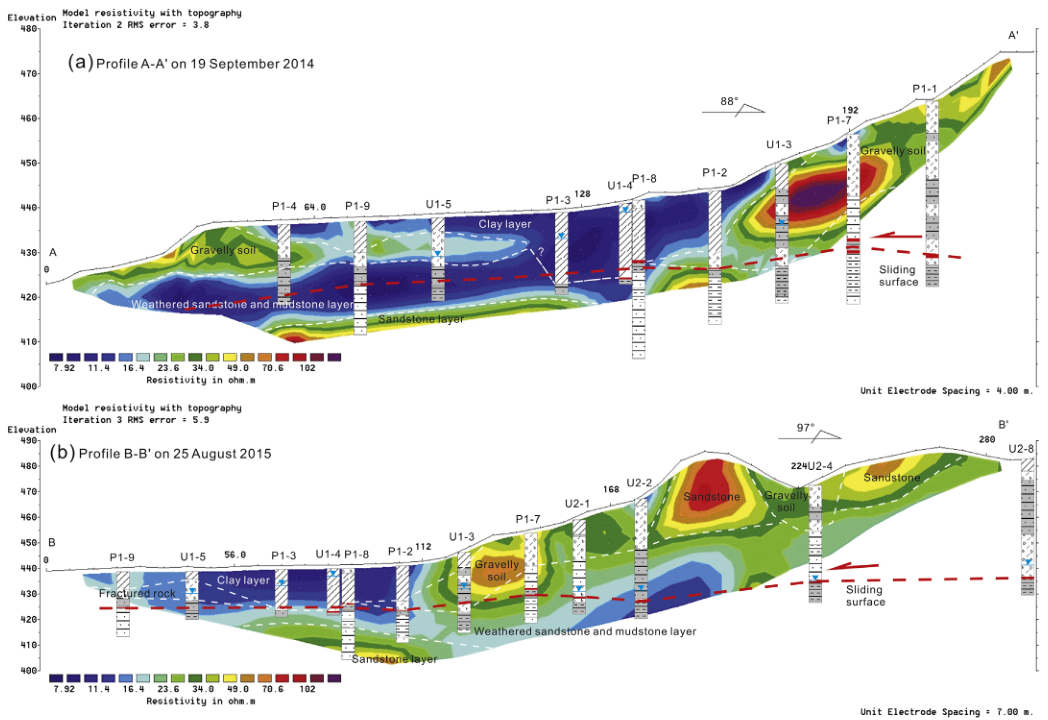
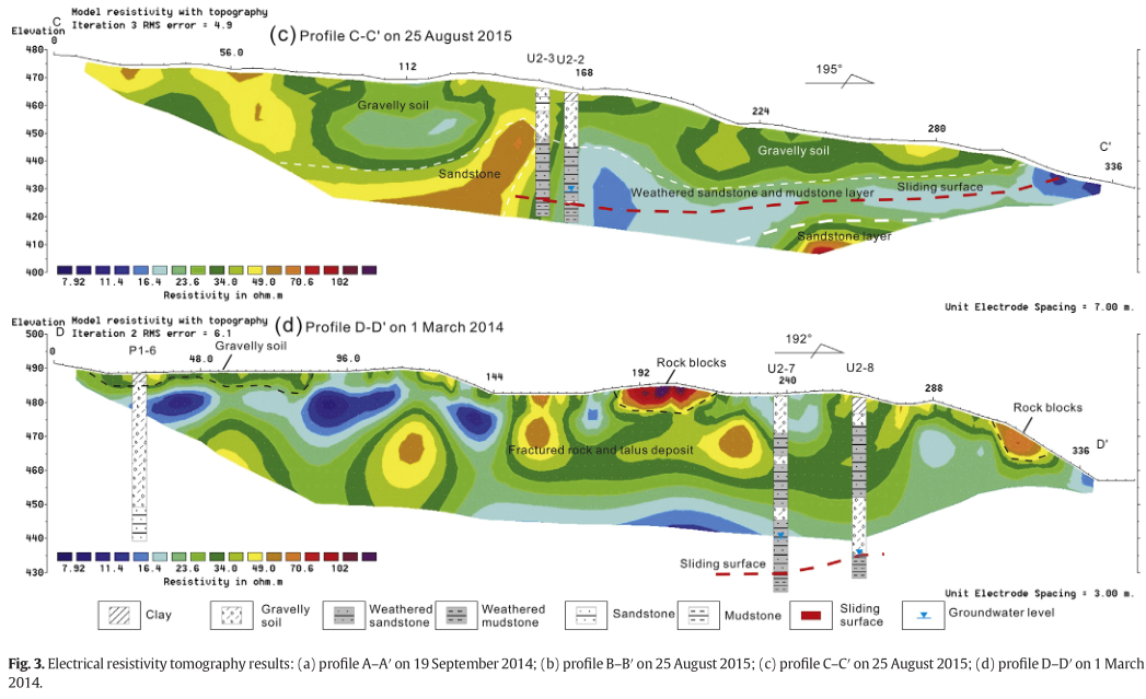
4.1. Results of the electrical resistivity profiles Fig. 3 shows the results of the four ERT profiles. The simplified logs and groundwater levels of the boreholes are also depicted on the resulting tomograms. The A–A′ and B–B′ profiles were arranged along the direction of the landslide movement, whereas the C–C′ and D–D′ profiles were measured perpendicular to the landslide movement. For the A–A′ profile, a shallow conductive layer (less than 15 Ωm) between 48 and 176 m coincided with the clay layer, which is used by locals for planting crops.The thickness of the clay layer changes from 3.0m(bore-hole U1-5) to 16.5 m (borehole U1-4). A deep zone of low resistivity (less than 15 Ωm), which corresponds to the sliding surface and sur- rounding weathered sandstone and mudstone layer, was verified usingthecoredata.Between28and140min theA–A′profile,theresis- tivityoftheslidingsurfacewas lessthan 10 Ωmwitha depthof approx-imately 15 m, which was verified from the P1-9 displacement data (Fig. 4). The dip angle of the sliding surface is generally consistent with that of the bedrock. A resistive layer underlying the sliding surface was observed, which corresponds to the bedrock that is comprised of sandstone. For the B–B′ profile, which had a larger unit electrode spacing (i.e., 7 m), the sliding surface between 0 and 112 m was located at the transition zone between the low resistivity (i.e., the sliding material) and high resistivity (i.e., the bedrock). Between 112 and 288 m, a shal- low resistive layer coincided with the gravelly soil and unweathered sandstone (greater than 50 Ωm), and the sliding surface corresponded to the deep zone, which had a low resistivity that was less than 30 Ωm. The thickness of the sliding material decreased from 50 m to several meters in the direction of the sliding. Due to topographic convenience, the C–C′ profile crossed two tension fractures with the NE–SW directions that were induced by the creepingofthelandslide(Fig.2).Theridgedresistivezoneof50 Ωmbe- tween 133 and 154 m could be interpreted as the sandstone between the tension fractures. The shallow materials (between 20 and 40 Ωm) are comprised of gravelly soil. The resistivity of the sliding surface was less than 20 Ωm due to the weathered sandstone and mudstone and the high groundwater availability. The thicknesses of the sliding materials decreased to several meters at the southern boundary (i.e., between 308 and 336 m). Theunconsolidatedformation inthetension troughsiscomprisedof weathered fractured rock, gravels, talus deposit, breccias, and soil that have a large range of resistivities (10 to100 Ωm). From thefield survey, the material with high percentages of soil showed local low resistivities (lessthan 40Ωm), e.g., atdistancesbetween 0 and 80m alongtheD–D′ profile. The material with a high percentage of rock blocks showed a local high resistivity (more than 50 Ωm), e.g., at distances between 186 and 216 m along the D–D′ profile. The thickness of the materials that filled the main tension trough was greater than the detection depth(approximately40m)intheD–D′profile.Thedepthofthesliding surface close to the main scarp is 46.10–52.40 m, according to the core samples from U2-7 and U2-8. The resistivity at the bottom of U2-7 was lower than those at the bottom of U2-8 because the groundwater level of U2-7 was 4.4 m higher than that of U2-8, which is closer to the gully.
Fig. 5 shows the geological profile of section II–II′ (Fig. 2) based on the geotechnical and ERT investigations. The sliding surface located at the weathered mudstone layer with low strength that belongs to the Penglaizhen group formed in the Upper Jurassic period (J 3p ). Three obvious tension troughs formed due to the slipping of the landslide. The former integral sandstone layer was cut off by the tension troughs, which were filled with colluvium comprised of rockblocks, gravels, and breccias(Q 4 col ).The middle and front parts of the landslide were covered by a layer of residuals and diluvials (Q 4 el + dl ), of which the ingredients are clay soil and gravelly soil. The thickness of the sliding material de- creases from 50 m to several meters from the rear edge to the toe
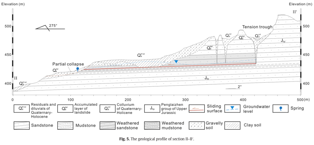
front of the landslide. The storage and transmission of groundwater on the sliding surface speed the weathering processes of the sandstone and mudstone and hence increase the porosity and permeability. Acon- tinuous and stable groundwater level has formed around the sliding surface. The groundwater level in the tension trough and at the middle part was the highest in the landslide.
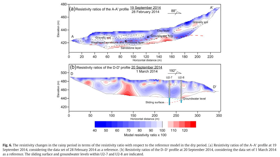
To study the characteristics of the groundwater circulation,theresis-tivity image measured in the dry period (i.e., 28 February 2014 and 1 March 2014 for the A–A′ and D–D′ profiles, respectively) was taken as a reference model, and the resistivity changes in the rainy period (i.e., 19 September 2014 and 20 September 2014 for the A–A′ and D– D′ profiles, respectively) in terms of a resistivity ratio with respect to thereferencemodelareshownin Fig.6.Ageneral decreaseinresistivity can be seen in the shallow layer of the two profiles, which is several meters thick. This decrease in resistivity is interpreted as an increase in water content related to the frequent rainfall in the rainy period. A significant resistivity drop was found at approximately a depth of 15 m in the A–A′ profile, which is consistent with the sliding surface in the weathered mudstone layer. The sandstone layer underlying the mudstone layer exhibited a slight increase in resistivity. These results imply that the groundwater recharged by the precipitation flows in the zone of the sliding surface and discharged to the toe front byseason-al springs. For the D–D′ profile, the stable groundwater level was out of range,andtheoveralldecreaseinresistivitywasdetectedasanincrease in water content due to the frequent rainfall in the rainy period.
4.2. Temporal variation in rainfall, surface displacement, and groundwater level Fig. 7 shows the daily data of rainfall, surface displacement, and groundwater level from 1 June 2013 to 31 December 2013. Rainfall is akeyfactorthatinfluencesthesurfacedisplacementandthegroundwa- ter level. In the rainy season (i.e., 6/1/2013–9/30/2013), the average values of the daily rainfall and surface displacement were 4.76 mm/d and 3.70 mm/d, respectively. In the dry season (i.e., 1/10/2013–12/31/ 2013), the average values of the daily rainfall and surface displacement were 0.65 mm/d and 0.46 mm/d, respectively. The maximum value of the surface displacement rate was 24.15 mm/d on 24 July 2013, after 259.5 mm of rain fell in a week. The groundwater levels of U1-1 (Fig. 7) and U2-7 (Fig. 6) in the tension trough were the highest in all of the boreholes and were approximately 10 meters higher than that closing to the leading edge (i.e., U1-5). The groundwater level decreases along the sliding surface at the rear part of the landslide (i.e., a distance from 150 to 194 m in the B–B′ profile in Fig. 3). The groundwater level at U2-1 was the lowest at the rear part of the landslide and was 10 meters lower than that in the tension trough. A reasonable explanation is that the locations of the boreholes in the tension troughs were close to the southern boundary of the landslide, and some ground- water could discharge to the southern boundary along the tension fractures with NE–SW directions.
The groundwater level of U1-4 was the highest at the middle- leading part of the landslide. The shallow depth of the sliding surface (i.e.,16.50–16.90m)andtheflatterrain allowed the ground watertore- charge easily from precipitation. The groundwater level of U1-5 closest to the leading edge of the landslide was the lowest in all of the bore- holes. The results of the resistivity variations and the groundwater level monitoring showed that the groundwater in the middle-leading part of the landslide is recharged by vertical infiltration and drains to the creek by springs (Fig. 1) along the sliding surface.
The groundwater levels of the boreholes respond to the rainfall by different modalities. The increment in groundwater level (i.e., U1-3, U1-4, and P1-3) measured at the leading-middle part of the landslide was less than 2 m and dissipated rapidly over several days. In the ten- sion trough, the thickness of unsaturated the colluvium is greater than 40 m. The water content of the colluvium is a key factor that influences the variation modes of the groundwater level. At the initial stage of the rainy period, the water content of the colluvium gradually increases to the upper water retention from the frequent rainfall, and the ratio of the groundwater level increment to rainfall increases simultaneously. For example, from 19 June 2013 to 28 June 2013, the total rainfall was 107 mm, and the ratio of the groundwater level increment to rainfall was 4.6. However, from 29 June 2013 to 10 July 2013, the total rainfall was 127 mm, and the ratio of the groundwater level increment to rain- fall reached 27.0. After the water content of the colluvium reached the water retention, the groundwater level rapidly and obviously responded to the rainfall. From 18 July 2013 to 25 July 2013, the total rainfall was 259.5 mm, and the maximum value of daily rainfall was 112.5mm on 22 July 2013.The groundwater level (i.e.,U1-1)in the tension trough rapidly increased by 9.28 m, and the ratio of groundwater level increment to rainfall reached 82.5, which implies that the ground- water wasmainlystored in the limited tension factures.The groundwater level dissipated slowly until October 2013. The variations in groundwater level in the tension trough indicated that the groundwater
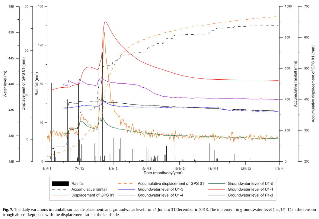
ran off mainly in the limited fissured medium and drained through the sliding surface slowly. The surface displacement rate increased to 24.15 mm/d on 24 July 2013. The rise in the groundwater level in the tension trough almost kept pace with the displacement rate of the land- slide, which shows that the driving force of the landslide is the positive pore water pressure (Fan et al., 2009; Xu et al., 2015).
5. Conclusions
Translational landslides are a typical geohazard in Southwest China. In this paper, four ERT profiles were conducted to investigate the internal structure in the southern region of the Kualiangzi landslide using drill cores and inclinometer data. The variation in the resistivities of two profiles and groundwater levels in boreholeswere usedtoevaluate the characteristics of groundwater recirculation within the landslide. In the ERT profiles, theslidingsurface waslocated in a deepzonewith low resistivity that corresponded to weathered sandstone and mudstone.
From the rear part to the leading part of the landslide, the thickness of the sliding material decreased from 50 m to several meters. The com- plex compositions, i.e., gravelly soil, weathered fractured rock, talus de- posit,andbreccias,ledtoheterogeneityintheresistivitiesinthetension troughs. The areas with low resistivity corresponded to materials with high percentages of soil.
The variations in the resistivity profiles in the rainy period with respect to the profiles in the dry period showed that a significant resistivity drop was found at the sliding surface. The groundwater level in the tension trough and at the middle transition part from the hill-country to flat terrain was the highest in the landslide. The groundwater level closing to the toe front of the landslide was the lowest. The results of the electrical profiles and groundwater level measurements showed that thegroundwater is recharged by precipitation and generally drains to the toe front by seasonal springs along the sliding surface. The groundwater levels in different parts of the landslide respond to rainfall in different modes in the rainy period. When the water content of the colluvium reaches the water retention, the rapid and large increment in groundwater level in the tension trough kept pace with that of the displacement rate after intense rainfall. The groundwater is stored in the limited fissured medium at the rear part and dissipated slowly over two months. However, the groundwater level at the leading- middle part of the landslide increased by a small value and dissipated rapidly over several days. The improved understanding of the internal structure and groundwater recirculation is beneficial to analysis of mechanisms and for hazard prevention in the translational landslide.
 ENGLISH
 Chinese
 Russian

