Reduce and Stop Water Accident of the Working Face by Grouting Cement Mud to the Near Fault
ABSTRACT
The 6 # working face of one coal mine of Henan Province in China is near a large fault, its water-resisting layer of floor is thinner and groundwater is abundant, the upper pressure is lost where the coal is mined-out, then the water-resisting layer of floor is fractured at the action of the powerful water pressure, and the lower underground water break through from the floor fracture into the 6 # working face. In order to exploit the 1.0 million tons of coal near the 6 # working face, cement mud is designed to grout into the fault to reduce and stop water. First of all, nine measuring lines are arranged parallel or perpendicular to F20 fault in the ground surface, the line spacing distance is 50m, and electrode spacing distance is 5.0~10.0m, and the underground lithological characters and accurate position of the joint line of F20 fault and 2 - 1 coal bed are surveyed according to the difference of electrical resistivity, then four holes named zk1 to zk4 are drilled which are 10~30 m south to the joint line, and better grouting effects of about 99.17% are obtained and the coal of 6 # working face can be exploited again . And this paper provides references for dealing with the similar project that are paused by water accident.
KEYWORDS: High density electrical method; water accident; coal floor; grouting; cement mud
INTRODUCTION
High density electrical method has a lot of advantages such as one-time arrangement for electrodes and multiple data collection, it has explicit theories about data process and integrated analysis technology of inversion results, it becomes one kind of common and efficient geophysical prospecting method, and now it has been used widely in latent fault detection, karst survey and tunnel advanced prediction [1-5].
One coal mine in Henan Province of China is a little mine with production of 0.5 million tons of coal per year, there is a large fault named F20 near the 6 # working face, the coal exploitation cannot be continued because of the abundant water breaking through the floor from the F20 fault, and this segment around the 6 # working face keeps about 1.0 million tons of coal. In order to exploit this segment of coal, the existing grouting technique and engineering example [6-8] are studied and conferred, a technology is put forward about drilling holes from the ground surface to the fault and grouting cement mud to the fault to reinforce the fault and then reduce and stop the water.
FAULT DETECTION
Water Accident
Geological structures develop comparative near the segments around the 6 # working face, and the water-proof rock of the floor of 2_1 coal bed are mainly composed of sandstone or mudstone with thickness of 1.0~4.0 m, which are much thinner. When the coal of 2_1 coal bed is mined out, the loads on water-proof would be removed, the water-proof layer are crushed at the larger water pressure and then abundant water broke through from the F20 fault into the 6 # working face. Although six pumps with power of 600 t/h are used to drawing water from the 6 # working face, abundant water poured in and the exploitation can not be continued, so how to reinforce the fault and reduce or stop the water accident is the most task for this coal mine.
Principle of High Density Electrical Method
High density electrical method is one kind of array exploration, assembles the advantages of electric profiling and electrical sounding method, works more efficient, and has more achievements in the world. High density electrical method is based on electric exploration and belongs to geotechnical electrical difference, and it is usually applied to study the distribution characteristics of underground current conduction under the given electric field and detect underground geological structures.
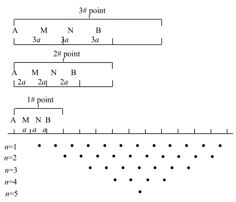
The data acquisition process and working principle of high density electrical method are shown in Figure 1 and 2 [1-5].
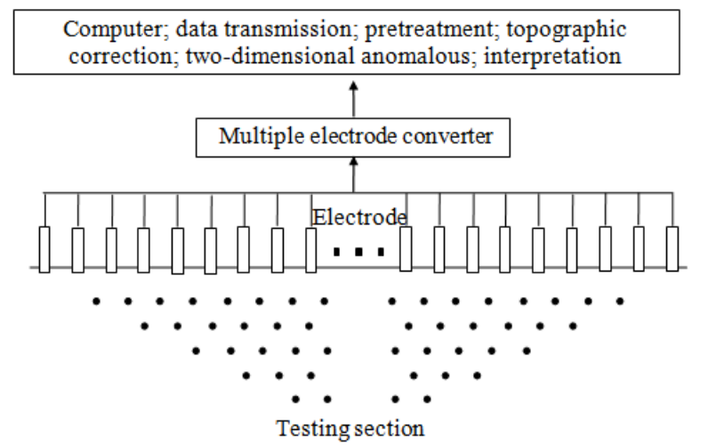
Figure 1: Data acquisition and data processing of high density electrical method
Figure 2: Working schematic diagram of high density electrical method (wenner device)
Detection of the Joint Line of Coal Bed and Fault
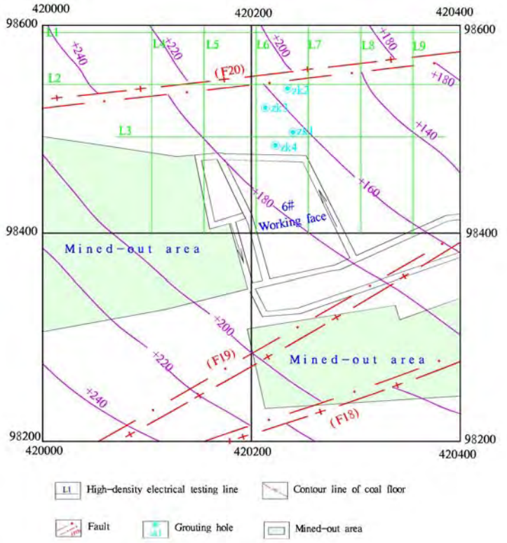
Figure 3: Arrangement of the testing lines and grouting holes at the ground
Large amount of water broke through the coal floor from the near F20 fault and the velocity is much large, and the grouting cannot be operated directly at the 6 # working face and can only on the ground surface, so to detect the accurate position of the joint line of coal bed and fault is the most important task.
Nine testing lines are arranged at the ground surface with spacing distance of 50 m, parallel lines of L1, L2 and L3 are in the direction of east-west, parallel lines of L4, L5 and L9 are in the direction of north-south, and parallel lines of L6, L7 and L8 are in the direction of south-north, and then electrodes are arranged along each testing line with spacing distance of 5.0~10.0 m. Testing lines are arranged as shown in Figure 3.
Instruments of “WDJD-2 multi-function DC excitation” and “WDZJ-1 multiple electrode converter” are adopted, the measured data are inversed for 5 iteration, and then the inversion result diagrams are obtained, as shown in Figure 4. There are no fault information in L1 and L3, and these two lines are not given in Figure 4.
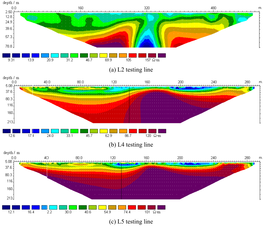
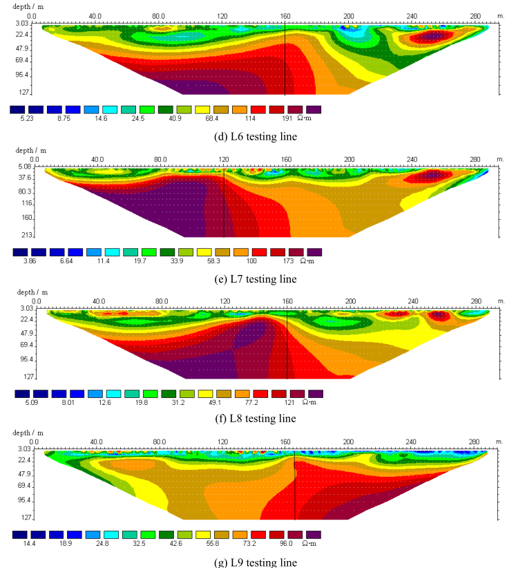
Figure 4: Inversed diagrams with high density electrical method
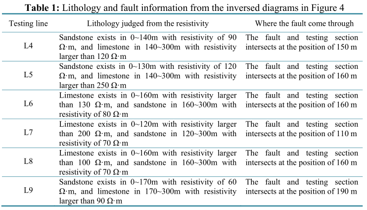
By analyzing and comparing the resistivity difference in Figure 4 and local geological data, we can find that, (1) L2 is tangent to the fault, whose slip is about 90 m and head is about 50 m; (2) the lithology is different along L4, L5, L6, L7, L8 and L9, which mainly includes limestone and sandstone, the fault intersects with the testing lines at different position, and the detailed results are shown in Table 1.
GROUTING TECHNOLOGY AND EFFECTS ANALYSIS
Grouting Technology
According to the observation and geophysical survey results as shown in table 1, four holes named zk1~zk4 are arranged about 10~30 m south to the joint line of F20 fault and 2_1 coal bed, the hole depths are designed to 180~200m, and the arrangements of zk1~zk4 are as shown in Figure 3.
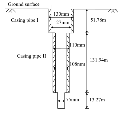
Figure 5: Typical drilling structure (zk1)
Firstly zk1, zk2 and zk3 are drilled and grouted in sequence, zk1 is also a geological validation and hydrology observation hole, then zk4 is drilled, which is used to examine the grouting effects, and zk4 is grouted whether or not is based on the grouting effects of zk1, zk2 and zk3 .
The drilling procedure includes three parts: (1) drill the hole with diameter of 130 mm and install casing pipe I with diameter of 127 mm before drilling through quaternary layer that composed of soil, gravel, sandy mudstone and shale, (2) drill with diameter of 110 mm and install casing pipe II with diameter of 108 mm until the 3.0 m below the coal floor, (3) drill with diameter of 75 mm to the designed position. And the total drilling structure of zk1 is taken as an example, which is shown in Figure 5.
The top-down piecewise grouting method is adopted when grouting cement mud in zk1~zk3, the ratio and concentration of cement mud must be controlled and adjusted in time according to specific circumstances.
When grouting pressure reaches the standard, then finish the grouting and sealing the hole with cement mud with water cement ratio of 0.6:1, and bury an orifice mark at the ground beside the hole.
The typical drill column of zk1 is given in the appendix.
Grouting Operation and Reinforcement Effects
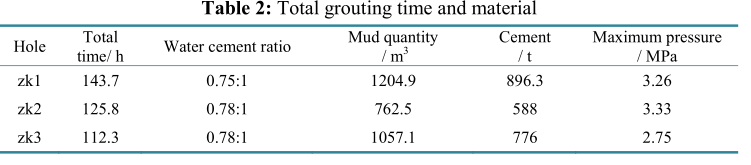
It takes about six months for the whole grouting construction, the total drilling length is 772.63 m, total length of casing pipe I is 223.15 m, and total length of casing pipe II is 552.5 m, zk4 is only an examine hole and not be grouted, and the grouting time and material of zk1, zk2, and zk3 are shown in table 2.
Karsts and fissures develop in the limestone section, so water slack phenomenon is common during the grouting operation in zk1, zk2 and zk3. The fissures in the rock cores drilled from zk4 are almost consolidated to be an entirety by the cement mud, but there is no water slack takes place again when injecting water into zk4 to examine the grouting effect, that is to say that karsts and fissures of F20 fault near the 6 # working face are almost filled with the cement mud in zk1, zk2 and zk3.
There is slight amount of water break through in the 6 # working face, and they can be pumped out with only one pump with power of 30 t/h, this segment of coal can be exploited again and not be affected by the water any more, and the stopping effect of water reach 99.17%, which is calculated on the ratio of one pump with power of 30 t/h to six pumps with power of 600 t/h.
CONCLUSIONS
(1) High density electric method is adopted, nine testing lines are arranged at the ground surface with spacing distance of 50 m, electrodes are arranged along each testing line with spacing distance of 5.0~10.0 m, and the accurate position of the joint line of F20 fault and 2_1 coal bed are determined by analyzing and comparing the diagrams inversed from the nine testing
lines.
(2) Four holes named zk1~zk4 are arranged about 10~30 m south to the joint line of F20 fault and 2_1 coal bed, zk1, zk2 and zk3 are drilled and grouted in sequence, then zk4 is drilled, and the grouting effects of zk1, zk2 and zk3 are examined to be perfect by the core rocks of zk4 and injecting water into zk4. Although there is slight amount of water break through into the 6 # working face, the exploitation operation can be continued again by pumping the water out with one pump with power of 30 t/h.
 ENGLISH
 Chinese
 Russian

